- Introduction for dummy
- 3 methods to measure a current
- Resistive current sensor Shunt method
- Ac galvanically isolated current transformer sensor method
- Inductive Hall Effect current sensor method
- How to measure current with an Arduino board
- Simple shunt resistor method
- Kelvin connection for shunt current
- Differential vs single current sensor amplifier
- High side vs Low side current measurement
- Integrated circuit to measure a current with a shunt series resistor
- Ac only isolated transformer method
- Ac/Dc galvanically Isolated Analog Hall effect method
- Digital bus resistive shunt method
- Differential High side shunt method
- how much time this article worth ?
- Links & Credits
Introduction for dummy
what is an electric current
In simple, an electric Current is a flow of electrons (negative particle) or ions (positive/negative charged particle) from one point to another of the matter (everything from metal to water or any other materials, even free space).
This eletctrons/ions are moved by a force called Voltage (as a difference of voltage/potential between two points in the matter). More is the Voltage, or weak the resistance of the matter, more flow of current you will obtain.
Direct vs Alternate current
A direct current, called DC, is a current that change very little, in term of volume of flow, during the time. You can generate a Direct Current using a battery applied to a resistor (battery and resistor have very stable value, aka are not much variable).
Alternate current, called AC, is a current that change over the time. You always use an alternate current when you plug your battery charger into an electrical socket.
One important Alternate current has a form, when his value is plotted over time, of a sinusoidal wave. This type of current is important because is mainly used in our appliances and, in general, in our life.

3 methods to measure a current
Resistive current sensor Shunt method
This method was the very first way to measure a current. This method use the power of the Ohm’s law that say: a current trough a resistor develop a voltage.
You can calculate this voltage by this simple formula: Vshunt = Rshunt * I.
This method, at least for high current, must use a Not Inductive resistor, because an impulsive current develop a voltage impulse that can broke analog input used in microcontroller or operational amplifier.

Ac galvanically isolated current transformer sensor method
In the past, when you was in need to “translate” an AC current into a DC current to allow to measure the current with a microcontroller, you would have used an AC current transformer.
Basically is a toroidal inductance where in the hole you put the wire that transport the current you want to measure. This become a transformer that take a partial of the main current by the ratio between numbers of turn in the toroidal inductance versus turns of main electrical wire.
In the case below turns for the main current wire is 1, where turns in the toroidal inductance are 12.
For example if main current is 120 ac Amp, the current from the toroidal output would be 10 ac Amp.
All the current that you take out from the main circuit will be wasted/subtracted to the main current.


Inductive Hall Effect current sensor method
“In 1879 Edwin Hall was exploring interaction between a magnetic field and an electric current, and discovered the Hall effect while he was working on his doctoral degree at Johns Hopkins University“.
When an electric/magnetic field is applied to a flowing current, his direction will deviate from the straight path. This could generate a differential potential/voltage that you can measure as a direct relation between current vs voltage.

How to measure current with an Arduino board
An Arduino board has at least an Analog to Digital Converter that “translate” an Analog Signal into a Digital Number, wathever is the sensor used. You have to take care of the voltage levels between analog sensor output and AtoD coverter input. Some Arduino board like UNO has a 5 Volt bus and therefore the maximum voltage output of your sensor must not exceed 5 Volt. Arduino board equipped with an ARM microcontroller has a 3.3 Volt bus and therefore the maximum voltage output of your sensor must not exceed 3.3 Volt. In case your sensor transfer his signal value via a digital bus, like i2c or SPI, you have any problem with sensor output voltage.
Simple shunt resistor method
This method is the very first way to measure a current. This method use the power of the Ohm’s law that say: a current trough a resistor develop a voltage.
You can calculate this voltage by this simple formula Vshunt = Rshunt * I.
For example if I need to measure a 1A full scale current with an Arduino UNO board, and I use 5 Volt as AtoD converter reference I need a resistor of:
Rshunt = Vshunt / I
in this example Rshunt will be 5V / 1A = 5 Ohm
You have to check the maximum power allowed by your Shunt resistor. For this example Power dissipated will be 5V * 1A = 5 Watt. I suggest to use at least a 10 Watt power rated resistor.


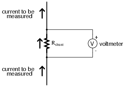
Kelvin connection for shunt current
When current gets high we have to use a Kelvin connection. This connection is simply a duplication of a connection as you can see from images that follows. This connection lower error due to PCB trace resistance.
This type of connection is called also “four wire connection”.

Differential vs single current sensor amplifier

High side vs Low side current measurement
The simplest and low cost way to measure a current with a shunt is to use a low side setup. This method introduce an error into the path of the current, due to some unwanted resistance in his path. If you need to simultaneously measure accurately voltage and current this is not a good method.
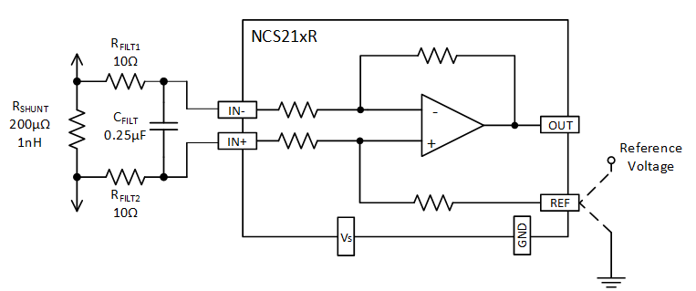
Integrated circuit to measure a current with a shunt series resistor
there are many chips that could be directly connected and used with an Arduino board analog input. Some examples follow.
You have to choose which parameters are important for your project:
- High speed
- High accuracy/precision
- Low cost
- Which maximum bus voltage you have
- Which maximum current you have to measure
- Uni-directional or Bi-directional current flow (last used for battery measurements)
Max471 chip is a bi-directional differential High side current sense amplifier with integrated shunt resistor (no need to use external resistor) and very low supply current up to 100 micro Amp. You can monitor both charge and discharge of a battery. Maximum input current is +/- 3 Amp. Output is an analogic signal that you can measure with an Arduino analog input.
You can buy this clicking on the link below:
buy a MAX471 current sensor module +/- 3 Amp for Arduino

Ac only isolated transformer method
You have to use this kind of current sensor when you need to be safe and isolated from ac high voltage power supply.
An arduino ADC input works with a DC voltage, instead alternate current transformed by the sensor is alternated, and therefore not directly compatible.
You have to bias voltage from the current transformer sensor. This bias voltage will be half of the full scale input ADC voltage.
In case of Arduino UNO board with an ADC reference of 5 Volt, your bias should be 2.5 Volt.
For an Arduino ARM based board with an ADC reference of 3.3 Volt, your bias voltage should be 1.65 Volt.


You can buy an Arduino module clicking on the link below:
Ac current transformer module for Arduino like board

Ac/Dc galvanically Isolated Analog Hall effect method
There are some integrated circuit with hall effect sensor, to use for galvanically isolated current measurement applications, that you can use directly with an Arduino microcontroller like board.
With these chips you can measure a DC or AC current directly and measure the value with an ADC analog input from an Arduino like microcontroller board.
You can directly measure an AC current galvanically isolated, aka safe mode, or a switching current.

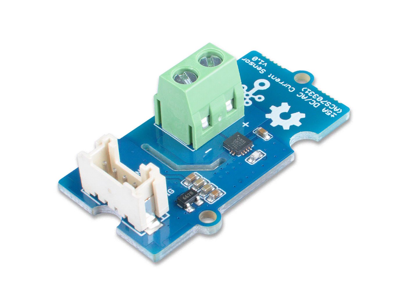
A widely used Hall effect sensor in Arduino community is the ACS712 module populated by a chip from Allegro microsystems, a well known brand.
You can buy this module at good price and proved seller clicking on the link below:
ACS712 Hall effect current sensor for DC/AC galvanically isolated measurement
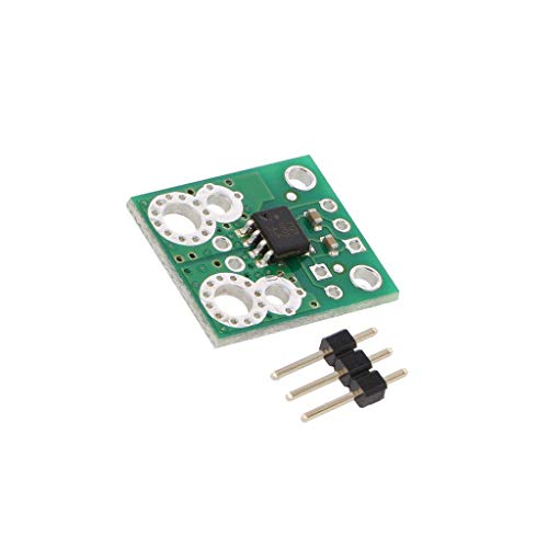
You can buy a Pololu Hall effect module clicking to the link below:
ACHS7121 current sensor bi-directional +/- 10 Amp
Digital bus resistive shunt method
There are some current sense amplifier that provide the current value directly in a digital format trough a digital trasmission via i2c or SPI. These chips are useful because you have already a converted value without need to make any calculation.
They are equipped with an AtoD converter and you do not need to use an Arduino analog input.
These chips can measure even the voltage and calculate the power consumption.
To use this chips with Arduino you have to use a compatible library.
INA219 is able to measure current and voltage bus, and it calculate for you consumed power. Adafruit introduced this chip early and provided a well known library for Arduino.
You can find tutorial and library directly from Adafruit or click to the link below:
INA219 Arduino library & tutorial
You can buy this breakout module ready for Arduino directly from Adafruit clicking to the link below:
Buy INA219 current +/- 3 Amp & voltage sensor 26 Volt max breakout board for Arduino

INA226 is a Ti chip that can measure current and voltage with a 16 bit resolution and transmit all measured values with an i2c bus directly to your Arduino board with no need to use an analog input.
You will need to install an INA226 Arduino library on Arduino IDE before you use this current sensor. You can find many libraries clicking to the link below:
GitHub libraries for INA226 Arduino current sensor
Arduino IDE libraries have this driver in his list. You have to pick this library from Tools -> Manage Libraries and search for INA226.
You can buy a ready to use breakout board module clicking to the link below:
buy an INA226 current sensor breakout module for Arduino


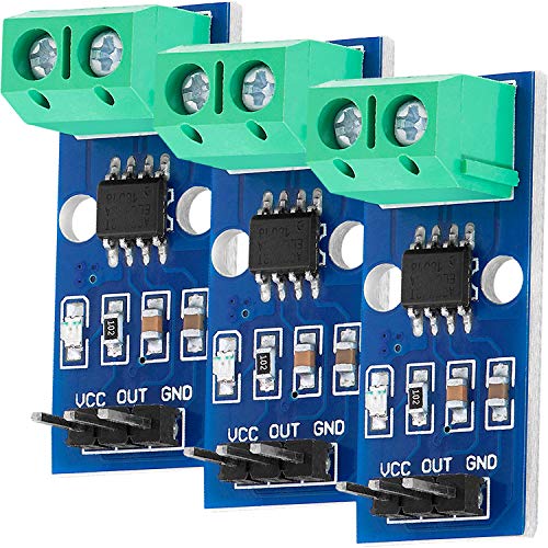
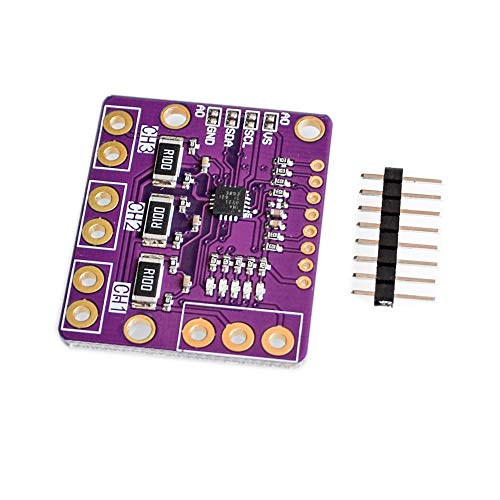
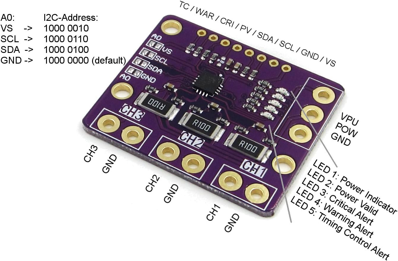
INA3221 chip is a triple current/voltage sense amplifier that provide to your Arduino a ready made measures that you can get from i2c bus. This chip is useful in a BMS system when you have 3 batteries stacked in series.
To use this module you have to install an Arduino library. You can find this clicking on the link below:
You can buy a 3 channel current sense amplifier module for Arduino with Ti INA3221 chip i2c bus clicking the link below:
INA3221 triple channel current sensor for Arduino
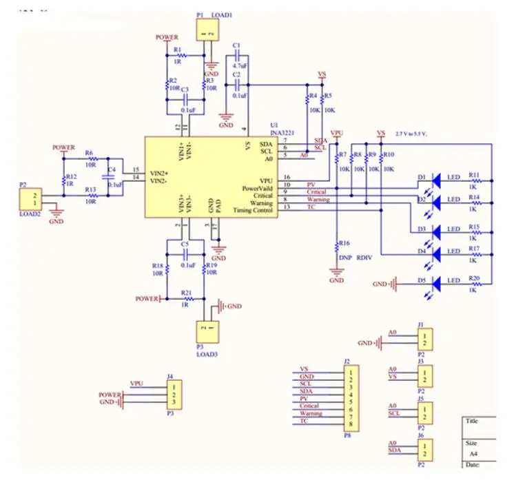
This breakout has all 3 channels with ground in common, this means that you cannot use 3 channels in floating setup. You can see the circuit diagram below.
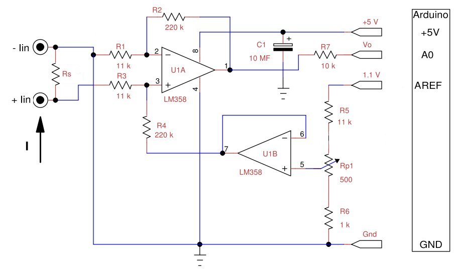
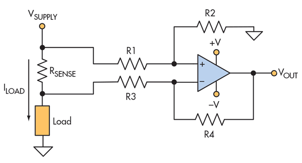
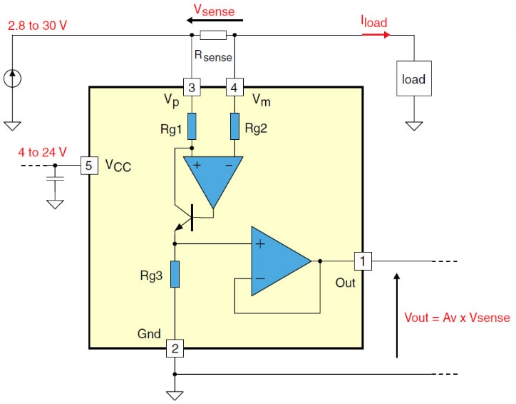
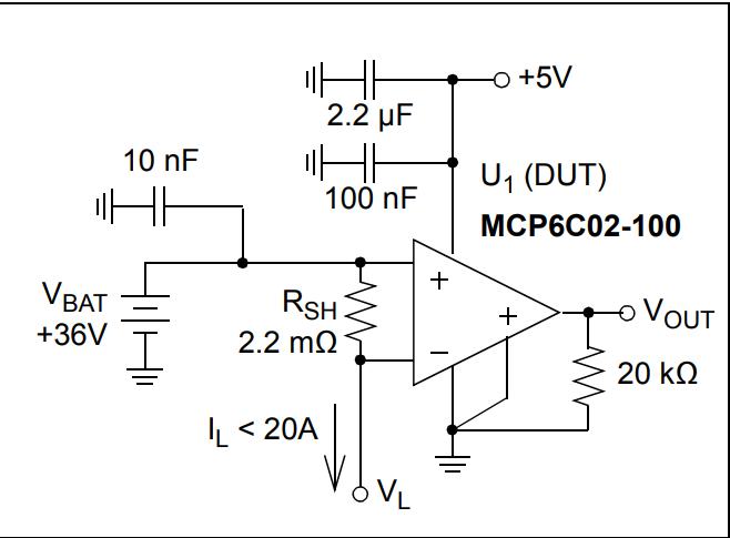
Differential High side shunt method
When you need to measure accurately current and power voltage, at the same time, you have to use a differential amplifier. If you like to make your high side current sense amplifier by scratch use informations provided before. Use a low offset amplifier, high precision resistors and try by yourself and make experience.
You can find info in these TI pdf:
Using An OpAmp for High-Side Current Sensing
High-side current-sensing circuit design


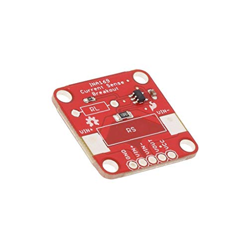
INA169 has an analog output compatible with an Arduino analog input. This current sense amplifier is able to work with a bus voltage up to 60 Volt consuming only 60 micro Amps. You can buy a breakout module for Arduino clicking to the link below:
Buy an INA169 breakout board for Arduino current sensor
The SparkFun breakout board give you the chance to choose the maximum current to measure. You have to populate this board with a shunt resistor RS and an full scale set resistor RL. You find all info in his datasheet that you can find at following link:
how much time this article worth ?
This is the time I spent to think, research and write down this content. I hope you’ll find useful informations.
Oct 23 2020 – 4h
Oct 24 2020 – 6h
To pay for site hosting I’m an Amazon affiliate and I have to disclosure this sentence: “In qualità di Affiliato Amazon io ricevo un guadagno dagli acquisti idonei”. I choose only to advertise products with a good quality and a proved seller. You will not be added any additional commissions to your buying. I hope you will find this a good service.
Links & Credits
What is an electric current ? by Wikipedia
Electric Current Transformer by Wikipedia
How hall effect works by Wikipedia
High voltage up to 400V high side current sensor circuit diagram
TI how to design with current sense amplifiers
Precision current sensing guide by ES components
Amplifiers for HEV/EV battery management systems by Power Electronic Tips


